
Print Set
Choosing the right speed for your print can be quite a challenge, especially if you are new to 3D printing. After a bit of trial and error, you’ll be able to guess a setting that will generally work. Still, you’ll have a lot of variation with your results. Finally, you might not be using your hardware at its full potential by randomly choosing values.
The print speed calculator has been developed to help you choose the right setting based on our experimental values. This blog will teach you the basics for understanding 3D printer extrusion, how we developed the calculator and why it can be very useful for you.
Using the right line width
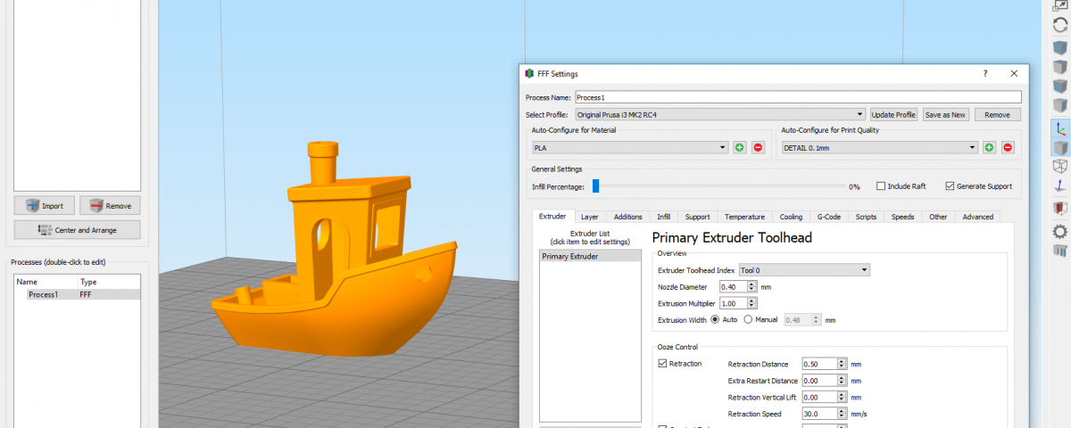
Line width is a critical parameter for a successful print. Most software will generally calculate it automatically, but you’ll soon realize it’s much better to configure it by yourself.
The slicer’s automatic calculation consider the nozzle size and increase it by 20%. A general rule of thumb accepted by 3D printer users suggest a line width up to 50% bigger than the nozzle. Although this generally works fine in most cases, you’ll see a big drop in print quality and consistency with bigger nozzles and layer height.
Figure showing a section view from a nozzle extruding a line of plastic
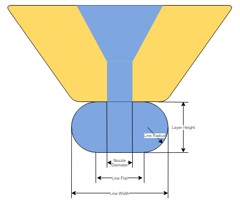
Understanding the extruded profile
The molten plastic is pushed in something like an oblong shape. For simplifications, we’ll consider a perfect oblong shape. This flattening ensures a good bond between the layer underneath or the bed. Extruding a perfect circle would make very weak since each layer would barely be touching each other.
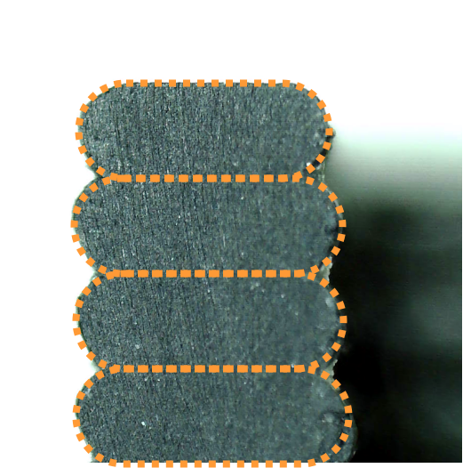
Too small line width
This oblong radius is equal to half the line height. The radius is changing with the layer height. The higher the layer height, the larger is the radius. At some point, the traditional 20% increase in line width can’t cut it and will under-extrude. Under extrusion happens when there is little to no line flat from the extruded oblong. The figure below shows an example where the extrusion has no flats. In this configuration, the layer height is equal to the line width. The line flat is equal to zero.
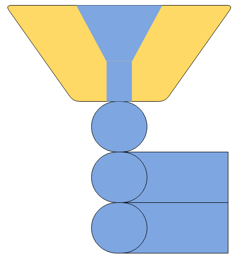
Minimum line width
The minimum line width can be considered when the flat width is equal to the nozzle size. This ensures that the oblong shape is properly formed and uniform.

For example, a 0.40mm nozzle with a 0.20mm should have a line width of at least 0.60mm.
The figure below shows a minimal configuration for line width.
Please note that the line width could actually be a little smaller than this suggested formula. The shape will slightly differ from the perfect oblong shape depending on the polymer flow. In most cases, a smaller line width is totally fine.
Maximum line width
The maximum line width will depend on your nozzle flat width. Manufacturers should specify this dimension to configure your slicer accordingly. The maximum line flat should be equal to the nozzle flat. Note that any overflow will have an impact on top infill quality, as it will tend to rise around the nozzle.

Considering a 0.40mm nozzle having a 0.80mm flat with a 0.20mm layer thickness have a maximum line width of 1.00mm.
The myths about layer height
It’s common to see that 50% of your nozzle size is the sweet spot for printing. This works totally fine in most printing situations. It’s also very frequent to hear that it’s not good or possible to go higher in layer height than the nozzle diameter.
Going bigger!
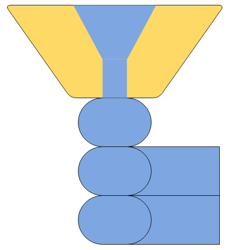
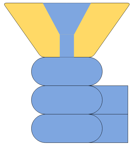
However, nothing is stopping you from going a lot higher or lower. For example, the two images below are the same exact Gcode, one ran with a 1.00mm nozzle, the other with a 0.40mm nozzle. The line height is 0.50mm and line width is 1.50mm.
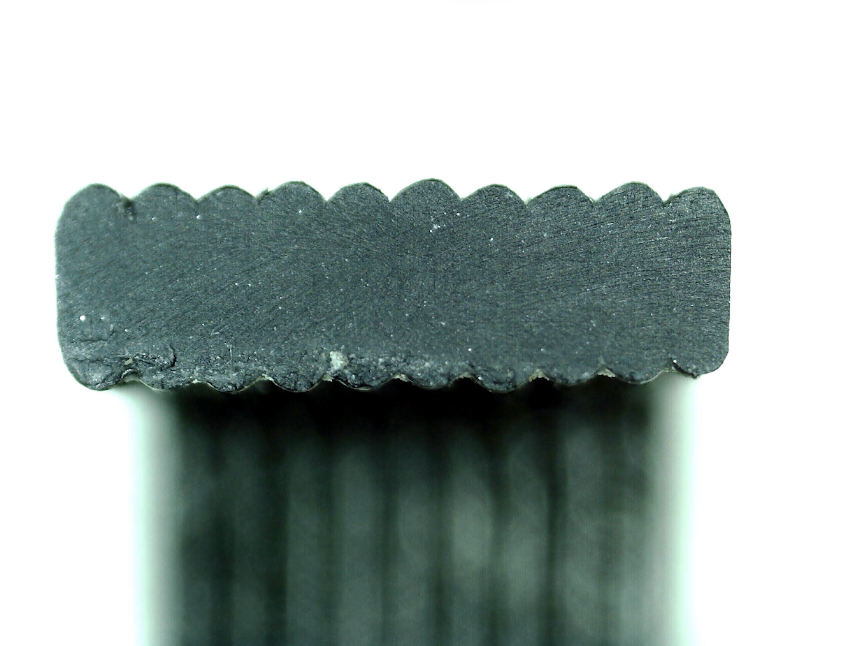
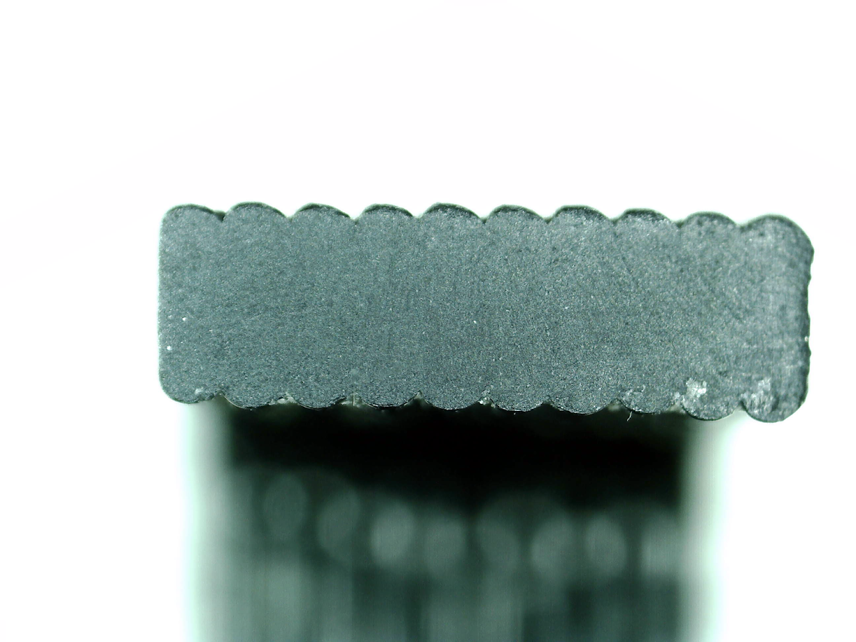
As you can see, there is barely any difference. As long as the 0.40mm nozzle flat is within the margin, the result is pretty good. In this case, the layer height was 125% the nozzle diameter.
Smaller nozzle can still extrude large lines, but have more flow restrictions compared to larger nozzles. The speed must be decreased to get the same results.
Going smaller!
A similar test was done using a 1.00mm nozzle, but with 0.05mm layer height. In this set-up, the layer height is only 5% of the nozzle size. The results are quite interesting. The picture below shows a 20mm diameter half-sphere side by side with an AA battery. The zoom is pretty high, and we still have a hard time seeing the layers.
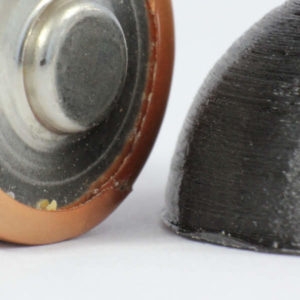
Printing with such a big nozzle reduces your detail level on the XY plane compared to a smaller nozzle. However, the line are very thick, thus greatly reducing the infill and contour printing time.
Choosing the right flow
Choosing the right flow will save you a lot of trial and error before getting consistent results. Polymer flow variation can be understood in the following way:
Increasing the line width, height or speed will increase flow
More flow means that the polymer is less time in the melting zone, thus extruding slightly colder
Combining the lower temperature and the higher shear stress generates a higher pressure
A higher pressure puts more stress in the filament and extruder
At some point, either the motor will start missing steps or the filament will grind, and the extrusion is not controlled anymore
There is always a small slipping in the filament from the extruder. The faster you go, the greater is the slipping. Below is an example taken from the DyzEnd-X with few nozzles. You can see that the 1.20mm nozzle can output a lot more flow than the other nozzles. Also, the efficiency is decreasing by an exponential rate based on the output flow.
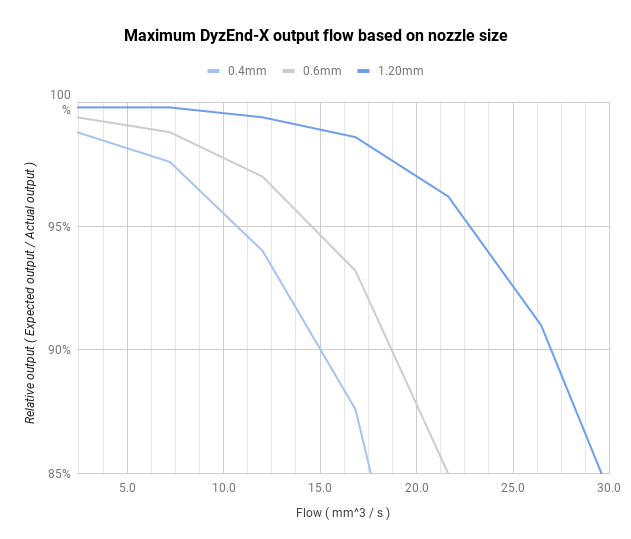
Taking this into account, it’s very important to choose the right speed and flow to get the same output. For example, doubling the flow from 5 mm3/s to 10mm3/s can reduce flow by around 3%. Same case with a 0.60mm nozzle will reduce flow by 2%, and less than 1% with a 1.20mm nozzle.
Flow calibration
Flow calibration is critical and the steps per mm must be precisely found. The values provided by the guide in support section gives a starting point. Due to manufacturing tolerance, this value can be different from one unit to another. It is suggested to calibrate your extruder without any hotend, as a baseline value for any users.
The print speed calculator
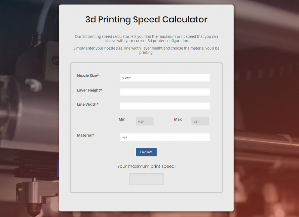
With all this knowledge, it’s now time to introduce the speed calculator. The goal of this tool is to offer the most precise slicer configuration for your 3D printer. The data comes from multiple experimental tests in different configurations:
Nozzle size
Material
Temperature
Hotend
Extruder
All these results were broke down into charts which are used in this calculator. Once you enter the desired layer parameters, the maximum printing speed is calculated. From this point, the user can choose a lower value if desired. The suggested flow is then adjusted based on the slower speed.
This flow adjustment is critical for dimensional accuracy. The pressure is reduced as the speed is farther from the maximum, thus requiring a slightly lower flow. Keeping the same flow for different speed might lead to a small difference in dimensions.
Printing with large nozzles can confuse some users as the speed might seems slow. In fact, when using a 1.00mm nozzle with a 0.50mm layer height and 1.50mm line width, the suggested speed is below 35mm/s. Many users would be tempted to guess this speed at a much higher value.
The experiments are still undergoing and the calculator will be improved with more choices and more precise values.
Conclusion
Choosing the proper parameters for speed and flow is quite an art. There are many rules of thumbs for helping in this task. However, as shown in this blog, they might not always be right or the optimal solution.
The print speed calculator has been developed for helping users defining their optimal speed and flow. This will greatly help improve part accuracy and consistency across materials and configurations.
I hope you enjoyed this article about this new tool. I’ll be happy to complete it if I have forgotten or mistaken any information. Feel free to comment it and share your thoughts.
Last updated
Was this helpful?